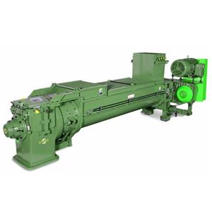
Double wall plough type continuous mixer
It is necessary to ensure that foamed acid (foamed dilute sulfuric acid formed after the liquid formed by mixing concentrated sulfuric acid, water and foaming agent is foamed by compressed air) fully wetts the lint on the surface of cotton seed, The mixing quality of cotton seed and foamed acid is directly related to the consumption of concentrated sulfuric acid, water and foaming agent, and affects the productivity of subsequent drying and defoiling equipment and the amount of residual acid in seeds.
Foreign similar equipment generally adopts horizontal rod-tooth mixing devices, such as those produced by Ramas Company and Western Equipment Company in the United States. Domestic similar equipment is a combination of rod-tooth and blade sections. The mixing and stirring length of such equipment is generally 10-15m. Due to site restrictions, some equipment has to be divided into two sections. The mixing and stirring capacity of these equipment is relatively weak. Although cotton wool surfactant is added to dilute sulfuric acid, in order to meet the technological requirements and ensure full wetting of cotton wool, the supply of dilute sulfuric acid must be increased and the length of the machine body must be lengthened, resulting in increased consumption of sulfuric acid, water and the like and huge equipment structure. However, the increase of sulfuric acid and water also brings adverse effects to the subsequent processes, because the increase of water causes difficulties in cotton seed drying and velvet removal, increases energy consumption for drying, and decreases output. The increase of sulfuric acid will lead to the increase of residual acid on the surface of cotton seeds, making neutralization of cotton seeds difficult, and some have to be neutralized twice.
Equipment Structure
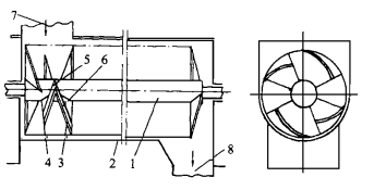

Fig. 1 Structure diagram of double-wall plow type material continuous mixer. Fig. 2 Layout of double-wall plough pieces. ( 1. Reverse Blade 2. Forward Blade )
As shown in Fig. 1, 1. Stirring rotor 2. U-shaped groove 3. Forward blade 4. Reverse blade 5. Plate making 6. Plate making 7. Feed port 8. Discharge port. The motor drives the stirring rotor to rotate through the continuously variable transmission, and the materials enter the U-shaped groove from the feed port, and are mixed and stirred evenly under the action of the double-wall plough piece and sent to the discharge port.
The material is divided into two parts by the ridge front composed of front and back blades in the machine, one part is pushed forward and the other part is pushed backward, thus causing the material to generate continuous axial reciprocating movement. At the same time, the copying board also shovels up and turns over the materials at different radii, causing intermittent radial movement of the materials. Therefore, under the joint action of the blades and the copying board, the materials are repeatedly turned over, diffused, stirred and kneaded in the machine, so that the materials are mixed evenly. Since the forward blade is larger than the reverse blade, the material moves slowly towards the discharge port in the overall trend when making axial reciprocating motion, thus meeting the requirement of continuous work. In addition, the material is changed from the usual one-way movement mode to reciprocating movement, which greatly shortens the length of the equipment and basically overcomes the problems existing in the rod-tooth equipment.
From the experimental results, it can be known that the length of the reverse blade is generally 1/2-2/3 of that of the forward blade. In order to ensure the radial flow of materials, a certain gap needs to be left between the double-wall plows. In order to make the stress on the shaft uniform, the double-wall plough piece should be arranged in a spiral line on the shaft, and it is better to arrange 1-2 leads on each shaft according to the double-headed spiral line. As shown in Fig. 2, in order to prevent the material from being squeezed at both ends of the body, only forward blades need to be set at the inlet end of the material and only reverse blades need to be set at the outlet end. When the mixing device consists of multiple stirring rotors and U-shaped grooves, the tail of each rotor and the head of the next rotor are only provided with forward blades, thus helping materials to smoothly pass through the connecting parts of the shaft. The plate is arranged in a spiral line on the front and back blades, which is beneficial to the movement and turnover of materials. Sufficient clearance needs to be left between the tail of the plate and the shaft to facilitate the flow of materials.