Forced conveying device with mixing function
1. Working principles
Forced conveying device with mixing function is one of the important equipment in plastic extrusion production line. The device adopts a screw with left and right rotation, driven by a deceleration motor. The materials at both ends of the screw are simultaneously transported to the middle of the screw by utilizing the conveying mechanism of the screw thread. When the materials transported in the left and right directions merge in the middle of the screw, some materials are forcibly transported to the processing equipment through the material conveying port which is in the middle of the mixing bin. Thus realizing the forced conveying function of the materials. Since the conveying capacity of the left and right threads is much greater than that at the material conveying port. Some materials will form an arched state in the middle of the screw. Due to the continuous replenishment of materials at both ends of the screw, the arched material in the middle will rise, and when it rises to a certain height, it will disperse to both ends, thus completing a cycle of mixing.


Fig 1: Working principle Fig 2: Left and right screw
2. Structural design
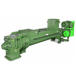
As shown in Fig 3, the forced feeding device with mixing function comprises a hopper 1, a feeding screw 2, a motor 3, a cylindrical material mixing bin 4 and a discharge valve 5. The top of the material mixing bin is provided with a feed port 6, and there is a discharge port 7 at its bottom. The feed and discharge ports are both in the middle position of the material mixing bin. The feed port is connected with the blanking port 8 of the hopper 1. The discharge valve is installed on the discharge port. The feed screw includes a rod body 201, and a forward thread section 202 and a reverse thread section 203 are arranged in sequence along the axial direction of the rod body. The thread directions of which are opposite. Both ends are rotatably installed on the two side walls of the mixing bin. The forward thread section and the reverse thread section are both located in the material mixing bin. Their junction points correspond to the positions of the feeding port and discharging port. The one end of the rod body exposed outside the material mixing bin is driven and connected with the motor.


Fig 3: Overall structure. Fig 4: Internal structure
As shown in the figure, the feeding speed of the forward threaded section and the reverse threaded section is set to the greater than the discharging speed of the discharging port in advance, the discharging valve is closed at the beginning of the operation, different materials are stored in the hopper in advance. And the materials enter the mixing bin from the hopper through the feeding port and fill its space. The motor drives the feeding screw to rotate in a certain direction, and the forward and reverse thread sections push the material to be transported from both ends of the feeding screw to the center. When the materials merge in the middle, the material arch upward and gradually rise due to the extrusion force from both ends to the middle. When the arched materials reach a certain height, they are dispersed to both ends for premixing. At the beginning of feeding, the discharge valve is opened. When the materials merge in the middle, due to the extrusion force from both ends to the middle, some materials are sent out from the discharge port, while the other part of the materials are arched upward and gradually rise. When it reaches a certain height, they are dispersed to both sides, thus completing a cycle of material mixing.
3. Conclusion
From the above working process, it can be seen that the forced feeding device with mixing function can realize the mixing and conveying of materials, i.e. The material mixing and conveying devices are closely combined, the structure is quite compact, the occupied space is small, which saves land resources. On the other hand, since the materials are immediately sent to the processing equipment from the discharge port after mixing, there is no intermediate conveying link, and the materials will not be stratified, thus improving the quality of the processed products. In addition, when the conveying of materials is blocked, the amount of materials transported downward will decrease and the amount of materials arched upward for mixing will increase, thus effectively avoiding problems such as motor overload caused by increased conveying resistance due to conveying failure.