Rotor-Stator Mixers: From Batch to Continuous Mode of Operation—A Review (1)
1. Introduction
A fully continuous mode of production is often desired in most types of industrial processing. Continuous production decreases the per unit cost of production and reduces the risk of quality differences between batches. However, batch processing is still commonly employed in many production lines, especially in the food, pharmaceutical, and cosmetics sectors.
Continuous production does introduce some additional difficulties. The first requirement is that each unit operation in the production process can be achieved in a continuous setup. Second, converting a given batch process into a continuous one requires an understanding of what (if any) differences there are between the batch and continuous versions of each unit operation. This second difficulty also applies to product development projects for continuous mode production, since laboratory testing is almost always performed in batch.
This review focus on liquid processing in rotor-stator mixers (RSMs), also known as high-shear mixers. RSMs, together with high-pressure homogenizers, are considered the standard tool for mixing and emulsification of liquid dispersions. High-pressure homogenizers are generally used for low to intermediate viscosity products and RSMs for products with higher viscosities [1]. Whereas high-pressure homogenization is an inherently continuous operation, RSMs can be operated in either batch or continuous mode. The same rotor-stator head is often used in both batch and continuous mode of operation, see illustrations in Figure 1 and Figure 2. Continuous mode RSMs are sometimes referred to as inline (or in-line) RSMs.
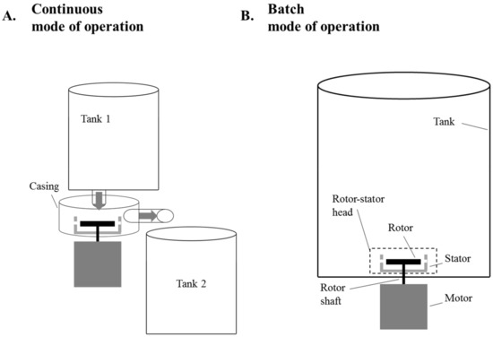
Figure 1. Schematic drawings of rotor-stator mixers (RSMs) operated in continuous (A) and batch (B) mode of operation.
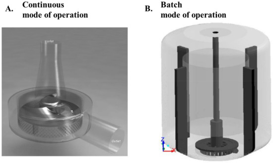
Figure 2. Schematics of RSMs for use in continuous (A) and batch (B) mode of operation.
From an industrial perspective, it is important to understand how the characteristics of a given batch mode RSM compare to those of a given continuous mode RSM. This understanding is crucial for both converting an existing batch production process to continuous production, and for generalizing results from laboratory (batch) experiments to pilot and production scale in a product development process. Since the rotor-stator heads are often very similar between batch and continuous modes of operation, it is tempting to assume that converting between the modes is straight-forward, both in terms of production economy (i.e., power draw of the rotor shaft) and in terms of obtained product quality (mixing or dispersing efficiency). However, as has become apparent in the scientific literature, this is not obviously the case [2,3]. Great care must therefore be taken when comparing RSMs run in batch to RSMs run in continuous mode of operation.
RSMs are used in many different applications, particularly in the food, pharmaceutical, and cosmetic processing industries. However, as pointed out in an editorial from 2001, despite their wide use, there has been a lack of fundamental understanding [4]. During the last 16 years there has been an increasing number of scientific research projects aimed at characterizing and understanding RSMs. Three major reviews have been published since then, summarizing many of these advances. In 2004, Atiemo-Obeng and Calabrese provided a comprehensive review of the mechanical designs of RSMs, focusing on power draw, flow profiles, and scale-up [5]. This review was also updated in 2016 [6]. Another fairly recent review has been provided by Zhang et al. [7], focusing on power draw and flow fields, but also providing an overview of the proposed emulsification scaling-laws and the mass and energy transfer correlations. However, none of these previous reviews provide a comprehensive discussion on the difference between batch and continuous mode of operation. Moreover, there has been a number of relevant studies on this in the last couple of years, after these reviews were written.
The objective of this contribution is to provide a more specific review on what is known about the similarities and differences between RSMs operated in batch and continuous mode, including the most recent advances. The intention is to provide an overview, both for engineering professionals struggling with the transition from batch to continuous rotor-stator mixing, and for the research community utilizing or studying RSMs. After a brief description of RSMs, this review will focus on four topics: The shaft power draw (power requirements) of batch and continuous mode RSMs (Section 3), the flowrate and pumping capacity of RSMs (Section 4), the pumping and turbulent dissipation efficiency (Section 5), and the implications of these differences on emulsion processing (Section 6). A summary of recommendations for further studies to resolve remaining issues is provided in Section 7, and the review is concluded in Section 8. Although RSMs can be operated under both laminar and turbulent conditions, this review will focus on turbulent RSMs, which are the most common RSMs employed in industrial applications.
2. The Rotor-Stator Mixer
The term RSM does not refer to a specific design but a range of mixer geometries [5]. RSMs are produced by several different manufacturers, and each have their own design, or more often several different designs for use with different applications, see References [5,7] for detailed overviews of different RSM geometries.
The common denominator of these RSMs is that they all consist of one or several high velocity rotors and one or several static stator screens separated by a short distance, the rotor-stator clearance, δ. The rotor accelerates the fluid tangentially and redirects it radially through the stator holes or slots. This gives rise to steep velocity gradients in the stator slot, or in the direct proximity of it, and creates a narrow region of high intensity hydrodynamics stresses [8,9,10,11,12,13,14,15], which give rise to high mixing and dispersing efficiency, characteristic of RSMs [14,15].
Although there are many different rotor-stator designs, they can broadly be classified into two groups based on the rotor: teeth-designs and blade-designs. A schematic view of the two design principles can be seen in Figure 3. As seen in the figure, the blade-design uses a rotor similar to that found in a centrifugal pump, either extending all the way from the shaft (as in the figure) or with shorter blades mounted on a plate attached to the rotor. The teeth-design uses a circular plate-mounted rotor, as seen in Figure 3. Both blade- and teeth-designs can use different stator screens (differing in the shape and size of the holes). Many rotor-stator heads also have multiple (i.e., 2–3) sets of concentric rotors and stators.
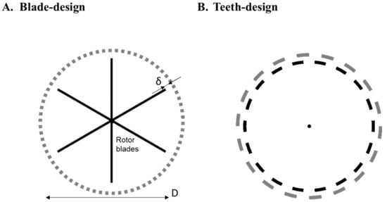
Figure 3. Schematic representation of a rotor-stator head with blade-design (A) and teeth-design (B). D denotes the rotor diameter, and δ denotes the rotor-stator clearance.
Figure 4 displays velocity profiles calculated with computational fluid dynamics (CFD) from two recently published investigations; one on blade-design [16] and one on teeth-design [11]. Looking at the general outline of the flow, there are many similarities. We can see how the fluid obtains a high tangential velocity in the rotor-stator clearance region, and how it is accelerated into a turbulent jet as it enters the (outer) stator slot. Note that the jet attaches to the leading edge of the stator and that the jet only fills a small portion of the slot [8,11,12]. This gives rise to a re-circulation region in the slots and, consequently, a “back-flow” of fluid that re-enters the slot from the bulk without passing the rotor [5,8,12,15,17,18].
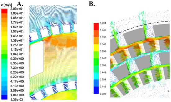
Figure 4.Velocity fields calculated using computational fluid dynamics (CFD) for two rotor-stator heads. (A) The flow field in a blade-design (Silverson RSM), reproduced with permission from [16], published by Elsevier, 2015; (B) The flow field in a teeth-design (Fluko RSM) from Xu et al. [11], reproduced with permission from [11]; published by Willey Online Library, 2013. Both show systems with two rows of rotor-stators.
The same rotor-stator heads are often used in both batch and continuous RSMs [3,19], the difference is primarily in how they are mounted, and how the product flow is subjected to the rotor-stator. In batch operation, the rotor-stator is mounted inside a mixing tank, either as an integrated part of the bottom of the tank as in Figure 1 (as is often the case in production-scale batch RSMs) or mounted on an impeller shaft lowered into the tank (more common for laboratory-scale batch RSMs). When used for continuous production, the rotor-stator head is mounted inside a narrow casing, similar to a centrifugal pump, with an inlet directing fluid towards the center of rotation and an outlet mounted at the periphery, see Figure 2.
Håkansson, A. Rotor-Stator Mixers: From Batch to Continuous Mode of Operation—A Review. Processes, 6(4), 32. https://doi.org/10.3390/pr6040032
© 2018 by the author. Licensee MDPI, Basel, Switzerland. This article is an open access article distributed under the terms and conditions of the Creative Commons Attribution (CC BY) license (http://creativecommons.org/licenses/by/4.0/).