Rotor-Stator Mixers: From Batch to Continuous Mode of Operation—A Review (2)
3. Shaft Power Draw
The economic benefit of using an RSM depends on the power draw, Pshaft, required to operate the rotor shaft at a given speed. Much attention has been put into investigating and predicting the power draw for RSMs.
3.1. Batch Mode RSMs
A batch RSM is principally an impeller mixer, and the power draw of such systems have been under scientific investigation since the 1880s. From dimensional analysis, it has been suggested that shaft power scales with rotor speed (N), rotor diameter (D), and fluid density (ρ):

Under turbulent conditions, the power number, NP, is constant with respect to impeller speed and diameter, but depends on tank and impeller geometry. Several studies have shown that Equation (1) is valid for batch RSMs. Fully turbulent, Reynolds number independent, power numbers are obtained above a critical Reynolds number of approximately 104, with Re defined based on the rotor tip-speed:

where µ denotes fluid viscosity. The power number NP is often found to be in the range 1–3, depending on the geometry of the rotor-stator head and the tank design. These values are often found to be in the same range or somewhat lower than the power numbers of Rushton type impeller mixers.
For impeller mixers, several experimental studies have also investigated and established mathematical relations for how the impeller and tank geometry influences NP. Less information is available for batch RSMs. The tank geometry is expected to influence the power draw less than in tank agitators, since most of the pressure drop occurs in the stator. Regarding RSM geometry, several high-quality investigations have been published, but they often compare commercial designs and it has been difficult to establish which geometrical difference is responsible for the observed effects. However, there has been two recent exceptions. One study focused on the effects of stator hole width (keeping all other design parameters constant) and suggests that NP decreases with increasing stator hole diameter for a single row Tetra Pak design. Another study, conducted on a range of commercial available Silverson designs, suggests that the NP is proportional to the square of the stator hole area. The discrepancy between these two different systems is still not understood.
3.2. Continuous Mode RSMs
For continuous mode of operation, the power draw is more complex as the flow through the RSM is not set by the system, as in the batch case, but can be varied over a large range by the processing equipment of the continuous line. Experiments reveal that power draw depends on both rotor speed and flowrate. During the last decade several experimental investigations, using a number of different RSM designs, have found support for a three factor model that describes the power draw:

where Q is the flowrate through the RSM. Equation (3) can be understood by considering that the continuous RSM is something in between a batch RSM and a centrifugal pump. The first term, Πrot is similar to that found for the batch design, and describes the effect of rotor speed. The second term, Πflow, is similar to the power draw of a centrifugal pump and describes the effect of flowrate. The third term, ΠL is a loss-term, representing the energy lost due to vibrations and losses in bearings.
Equation (3) contains two constants, NP0 and NP1. Just as NP for the batch RSM, these are design dependent but do not change with flowrate or rotor speed. NP0 is often found to be on the order of 0.1 and NP1 on the order of 10. See Table 1 for specific values of these constants for a few different RSM designs. Although several studies have compared NP0 and NP1 values for different commercial designs, no systematic studies describing the effect of different design variables have yet been reported.
Table 1. A comparison of power and pumping characteristics of some continuous mode rotor-stator mixers (RSMs).
| RSM | Power Characteristics | Pumping Characteristics * | Ref. | Figure 5 ** | |||||
| Rotor | Stator | Manufacturer | D (m) | NP0 | NP1 | c1 | c2 | ||
| Blade | Circular holes | Tetra Pak | 0.2 | 0.11 | 9.2 | 0.46 | −3.8 | [36] | I |
| Blade | Square holes | Fluko | 0.06 | 0.24 | 8.4 | 0.24 | −1.1 | [27] | II |
| Blade | Circular holes | Silverson | 0.12 | 0.1 | 6.4 | 0.44 | −3.2 | [34] | III |
| Teeth (1 row) | Teeth | Ystral | 0.12 | 0.13 | 9.7 | 0.23 | −2.4 | [34] | IV |
| Teeth (2 rows) | Teeth | Fluko | 0.06 | 0.15 | 14.5 | 0.13 | −4.5 | [27] | V |
Although Equation (3) has received substantial experimental support, it should be remembered that RSMs can be operated under a wide set of conditions and such designs differ substantially. A correction including a fourth and a fifth term has been suggested by Jasinska et al.. However, these extra terms only apply when operating the RSM at flowrates that are below what is typically used in commercial applications(p. 47), and can therefore often be neglected.
Equation (3) has been used with success for describing power draw in continuous mode RSMs manufactured by Fluko, Silverson, Tetra Pak, and Ytron. However, in one study, it was reported that for Conti TDS designs it is more appropriate to use a different correlation:

Note that N*P in Equation (4) is Reynolds number dependent, in contrast to NP0 and NP1 in Equation (3). It is still not completely clear why this difference is observed. The Conti design has no obvious geometrical difference when compared to the Fluko, Silverson, Tetra Pak, and Ystral mixers—for which Equation (3) is valid. The reported Conti design is with a slotted stator and a rotor with both teeth and blades, whereas the designs supported by Equation (3) range from teeth-designs to blades, and with a variety of different stator designs.
4. RSM Flowrate and Pumping
The net flowrate passing through the stator holes, Q, can be described in terms of a flow-number, NQ, via:
This applies for both batch and continuous modes of operation. However, it should be noted that the interpretation and controllability of this value differ substantially between the two modes. For a continuous RSM, flowrate is an externally set and easily measured parameter. Flowrate, and consequently NQ, can be adjusted by varying what is referred to as the system curve in pump design; the total pressure loss of the system the mixer is connected to. In practice, NQ can be decreased by using a valve downstream of the mixer or increased by adding a separate feed pump placed in series with the mixer.
When the mixer is operated in batch mode, however, NQ is a constant that depends on the geometry of the mixing head, and to some degree on the tank geometry. The NQ parameter is important for batch RSMs since it determines how fast the liquid is mixed. More specifically the expectation value for the time a fluid element spends in the tank between two passages of the rotor-stator head is:

where VT is the tank liquid volume.
Another difference between the two modes of operation is that Q (and consequently NQ) is difficult to measure for batch RSMs; it requires a non-intrusive experimental technique for measuring fluid velocities inside of and just outside of the stator slots, such as laser Doppler anemometry (LDA) or particle image velocimetry (PIV). Alternatively, it can be determined by a CFD model that has been validated by one of the above-mentioned experimental techniques.
Table 2 compiles values of NQ for a number of different batch RSMs and compares them to the NQ span resulting from operating some different continuous mode RSMs under technically relevant flowrates. As seen in Table 2, flow numbers are between 0.1 and 0.3 for batch RSMs. Systematic investigations are scarce, but based on a recent PIV investigation, it has been suggested that NQ decreases with increasing stator slot width. This phenomenon has been linked to the increase in backflow obtained when increasing the slot width.
Table 2. Flow numbers (NQ) for a number of batch and continuous mode RSMs.
| RSM | Rotor Speed, U (m/s) | NQ (-) | Method * | Ref. | |||
| Rotor | Stator | Manufacturer | D (m) | ||||
| Batch Mode of Operation | |||||||
| Blade | Rectangular slots | Tetra Pak | 0.2 | 3–14 | 0.11 | PIV | [8] |
| Blade | Rectangular slots | Tetra Pak | 0.2 | 3–14 | 0.11–0.15 | PIV | [9] |
| Blade | Circular holes | Silverson | 0.0028 | 3–5 | 0.22 | LDA | [12,38] |
| Blade | Rectangular slots | Silverson | 0.0028 | 6 | 0.18 | CFD | [17] |
| Blade | Square holes | Silverson | 0.0028 | 6 | 0.26 | CFD | [17] |
| Inline Mode of Operation | |||||||
| Blade | Circular holes | Tetra Pak | 0.2 | 20 | 0.02–0.06 | - | [3] |
| Blade | Circular holes | Silverson | 0.04 | 6–22 | 0.0003–0.037 | - | [39] |
| Blade | Circular holes | Silverson | 0.022 | 5–12 | 0.0003–0.0095 | - | [39] |
| Blade | Circular holes | Silverson | 0.0038 | 6–10 | 0.002–0.04 | - | [16] |
| Blade | Circular holes | Silverson | 0.12 | 13–19 | 0.0005–0.08 | - | [34] |
| Teeth | Teeth | Ystral | 0.12 | 13–19 | 0.0005–0.08 | - | [34] |
| Teeth | Teeth | Fluko | 0.06 | 5–10 | <0.05 | - | [27] |
| Blade | Circular holes | Fluko | 0.06 | 5–10 | <0.05 | - | [27] |
| * Method used for obtaining the flowrate through the stator slots in batch mode of operation: PIV (particle image velocimetry), LDA (laser Doppler anemometry) and CFD (computational fluid dynamics). (For continuous mode of operation, the flowrate is an externally measureable parameter). | |||||||
For continuous RSMs, NQ is substantially lower (NQ < 0.1); it is not uncommon that continuous mode RSMs are operated at a flow number one or several decades below that of batch RSMs. This implies that the flowrates through the mixer are substantially lower for continuous mixers compared to those through batch mixers. Using the same rotor-stator head and operating it at the same rotor speed will therefore result in much lower radial velocities in the rotor-stator region. This difference can also be explained using a centrifugal pump analogy. The flowrate is determined by the properties of the pump (what in pump-theory is referred to as a pump curve) and the properties of the system (the system curve). Since tanks used with batch RSMs provide a much lower flow resistance than the pipes used for continuous RSMs, the flowrate becomes substantially higher.
5. Pumping and Turbulent Dissipation Efficiency
RSMs are designed to deliver a narrow region of high intensity shear and/or turbulence in order to achieve efficient mixing and emulsification. Under turbulent conditions, this corresponds to delivering a high local energy density or dissipation rate of turbulent kinetic energy (TKE). When comparing batch and continuous mode RSMs, one should therefore keep in mind that the proportion of the supplied energy which can be translated into intense turbulence differs between the two modes of operation.
5.1. Batch RSM
For a batch RSM run under turbulent conditions, all of the shaft energy (except the losses, ΠL) must ultimately be dissipated as heat. This implies that the loss-free shaft power (P’shaft) equals the total dissipated power (Pdiss):
Not all of this energy is available for mixing or emulsification since these phenomena occur in a narrow region in or around the rotor-stator head. The energy that is dissipated outside of this high-intensity region will be an additional loss-term, seen from the point of view of the efficiency of converting energy into efficient mixing. Estimations of the local dissipation rates of TKE in a batch RSM have suggested that approximately 80% of the total dissipation occurs in the high intensity region (independent of rotor speed) for a one-row blade design [13]. This value is also close to the one reported from estimations from CFD simulations [12,17] for a similar geometry.
Assuming that the losses in bearings and those due to vibrations are negligible (ΠL/Pshaft << 1), the energy available for dispersion or mixing in a batch RSM, can be estimated directly by the power number:

Since the pump number is relatively easy to determine for a given batch RSM, it is also relatively easy to estimate how much energy is available for turbulent mixing and/or emulsification in a given batch design.
5.2. Continuous Mode RSMs
It is considerably more complicated to calculate how much energy is available for generating turbulence when running an RSM in a continuous mode of operation. In this case, energy provided by the shaft can take two routes: it can either be converted to turbulent fluctuations (and subsequently dissipated as heat), Pdiss, or it can be used for pumping, Ppump. In the latter case, energy is transferred to increase the average velocity or the static pressure of the fluid, often referred to as the “head” across the RSM [35]. These effects are summarized via:

Reformulated using Equation (3):
Note the difference between the Π-terms and the P-terms in Equations (9) and (10). Πflow and Πrot are the terms used in correlations to model power draw (Equation (3)), whereas Pdiss and Ppump are the power associated with the two underlying mechanisms of turbulent dissipation and pumping. As seen below, experimental investigations reveal that the terms in the power draw correlations do not translate directly into terms in the energy balance (e.g., Πflow ≠ Pflow). Again, further insight on the continuous RSM can be gained by comparing it to a centrifugal pump, where the pumping power is proportional to the flow-term in Equation (3) (Πflow) and a linear function of the flow number:

where c1 and c2 are constants that depend on the design of the centrifugal pump. A similar relation has been shown to hold true for several mixer designs. Figure 5A shows the linear fit of the right-hand side parenthesis in Equation (11), used to experimentally determined the pumping powers for five continuous RSMs using data from several different investigators, RSM manufacturers, and rotor-stator head designs. See Table 1 for values and design specifications.
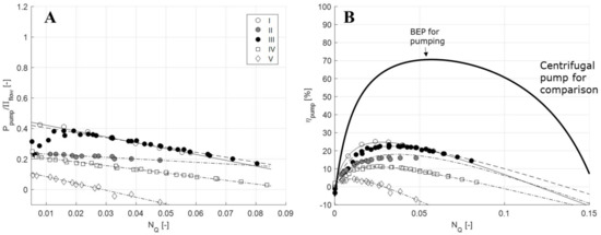
Figure 5. (A) Plot of Equation (11) to determine the pump constants c1 and c2 for the five mixers in Table 1. (Ppump denotes the pumping power of the mixer and Πflow denotes the flow-term in the power-draw correlation, see Section 5.2.) (B) Pumping efficiency (ηpump) as a function of the flow number (NQ) for the five mixers, compared to data for a typical centrifugal pump. Data from [27,34,36]. See Reference for the methodology.
Combining Equations (10) and (11) allows one to determine how much of the energy fed into the system is used for pumping (ηpump) and how much is dissipated as turbulence (ηturb):


Note that the efficiency is given by four empirically determined constants: the power draw constants (NP0, NP1) and the pumping constants (c1 and c2). These four constants are relatively easy to determine experimentally by measuring the power draw and the increase in head across an RSM for a range of different rotor-speeds and flowrates (see Reference for the power draw methodology and Reference for the pump-constant methodology).
Figure 5B shows the pumping efficiencies for the five different continuous mode RSMs from Table 1. The pumping efficiency of a centrifugal pump (LKH50, Alfa Laval, Lund, Sweden) has also been inserted as a comparison. Just as for the centrifugal pump, the percentage of energy translated into pumping in a continuous mode RSM (ηpump) varies with flowrate (NQ). For centrifugal pumps, the flowrate with the maximal pumping efficiency, often referred to as the best efficiency point (BEP) is always the desired operating point. However, for the continuous RSM, determining which flowrate is optimal will be considerably more complicated. The primary objective of the RSM is to transfer as much energy as possible into turbulence. This would suggest that a minimal ηpump (and hence a maximal ηturb) would be desired. However, continuous RSMs are often also designed to contribute to pumping the fluid; they are often used without external feed pumps. Hence, for most application a reasonable balance between pumping and turbulence efficiency is desired.
Note that the teeth-designs generally give rise to lower pumping efficiencies (see Table 1). One of the RSMs in Table 1 even gives a negative efficiency at high flowrates, implying that it is able to convert some of the power supplied from an external feed pump into turbulence. This suggest that teeth-designs are more desirable for applications where RSMs are not intended to contribute to pumping (i.e., when an external feed pump is used) and that blade-designs are more desirable for processes without an external pump.
Håkansson, A. Rotor-Stator Mixers: From Batch to Continuous Mode of Operation—A Review. Processes, 6(4), 32. https://doi.org/10.3390/pr6040032
© 2018 by the author. Licensee MDPI, Basel, Switzerland. This article is an open access article distributed under the terms and conditions of the Creative Commons Attribution (CC BY) license (http://creativecommons.org/licenses/by/4.0/).