Investigations on the Interaction Behavior between Direct Reduced Iron and Various Melts (1)
1. Introduction
In 2021, more than 1.8 billion tons of crude steel were produced worldwide. The integrated route Blast Furnace (BF)—Basic Oxygen Furnace (BOF)—is still the critical steelmaking strategy, with a share of more than 70% of the global steel production. The second most important steelmaking route is the scrap-based electric arc furnace (EAF) process. However, as the availability of high-quality scrap indicates, it will not be possible to meet the demand for steel without ore-based raw materials. Due to the limited potential for reducing CO2 emissions of the blast furnace, new iron ore reduction technologies are required.
A suitable technology is the hydrogen-based direct reduction process. Direct reduction (DR) refers to a solid–gas reduction reaction, for example, in a shaft furnace or a fluidized bed reactor. The ore, in shafts, either pellet or lump ore, is converted into the so-called sponge iron or direct reduced iron (DRI) as an intermediate product, which is typically melted in an EAF for further steelmaking. In 2020, about 104 million tons of DRI were produced, primarily based on natural gas (NG). Although this accounts only for a small share of the global crude steel production, it is a widely used steelmaking strategy, particularly but not exclusively, in NG-rich countries. Besides the EAF, processing sponge iron into pig iron using a submerged arc furnace (SAF) might be a second option. These aggregates are typically used to produce ferroalloys and process DRI made from ilmenite- or titanomagnetite-based ores into hot metal. Since it is expected that the described processing strategies will become more important, the behavior of sponge iron when immersed in liquids is of great interest for the optimization of the melting process.
The DRI properties and their influence on the EAF operation have been investigated extensively. Some key findings are summarized below.
Cárdenas et al. applied mass and energy balances to investigate various DRI scrap ratios and their influence on different process parameters. As sponge iron contained a higher proportion of oxides, the energy demand, slag quantity, and lime consumption increased. Further, a higher carbon content and a high metallization degree lowered the electrical energy consumption.
Kirschen et al. described a calculation model to analyze the influence of various DRI amounts on the EAF process. One of the key findings was the increasing energy consumption with a rising DRI fraction, resulting from the larger quantity of slag and endothermic reduction reactions with unreduced iron oxide. If the the carbon content in the DRI was carefully balanced, the oxygen addition remained relatively constant, but the yield decreased with more sponge iron in the charge. Furthermore, Kirschen et al. compared process data from 16 industrial EAF with varying scrap and DRI mixtures in a more recent study. Based on the results, a lower basicity is suggested to reduce the slag amount. Further, the MgO saturation must be considered when decreasing the basicity to avoid an increased wear of the refractory material. Compared to scrap charges, higher fluctuations in FeO content were measured for the slags. Possible explanations could be low metalized DRI fines and a decreased efficiency of the carbon injectors. As part of this study, the authors also optimized a previously published EAF model with respect to the application of DRI.
Lule et al. presented results from the ArcelorMittal Lázaro Cardenas melt shop, focusing on the behavior of nitrogen. High-carbon DRI was beneficial for making nitrogen-critical steel grades due to the extensive formation of CO bubbles.
Further, there are publications about industrial practices with high-DRI EAF charges. The following general conclusions can be drawn from these publications: a higher DRI fraction resulted in a rising energy consumption, especially when the acidic gangue content increased; due to the enhanced slag volume, the iron yield decreased as more Fe was lost in the slag; regarding tramp elements such as P or Cu, an increased DRI ratio was beneficial; furthermore, the metallization of the sponge iron should be as high as possible.
While most of the studies described above focused on industrial conditions, some publications analyzed the DRI melting and dissolution mechanisms at laboratory scale. Sharifi and Barati, as well as Li and Barati, investigated the reactions between DRI and steelmaking slags. The authors dropped DRI pellets into liquid slag pools and analyzed, e.g., the pressure increase in their furnace resulting from DRI–slag reactions. One significant result was that the decarburization involved two steps: reducing FeO in the DRI and progressing with FeO in the slag. Sadrnezhaad and Elliot conducted similar experiments. Beside the gas volume, also the temperature evolution in the pellet was measured. Based on the results, the authors described the formation of a solid slag shell on a cold sample. In a further study, this idea was used by Martínez et al. for the development of a melting kinetic model. The influence of carbon in the liquid on the melting behavior of solid metals was extensively investigated, e.g., by Szekely et al. and Penz et al.. Penz and Schenk summarized the current knowledge on this topic in a review paper. In addition to determining parameters such as the heat transfer coefficient, an important phenomenological finding is the diffusion-based melting process, i.e., the diffusion of carbon from the liquid hot metal into the solid metal. This decreases the latter’s liquidus temperature, a crucial step in the interaction between scrap and hot metal in the basic oxygen furnace (BOF).
This work aimed to analyze the interaction between a DRI pellet and molten metal directly after charging. DRI samples were dipped into liquid steel, hot metal, and typical EAF and SAF slags for a specific time period. While the previous studies described above focused on industrial, carbon-containing samples, in our case, DRI with 0%C was also considered. Subsequently, the immersed specimens were visually and metallographically examined and qualitatively compared concerning the interaction behavior between the sponge iron sample and the melt. The detailed comparison of the different model cases is a novelty for studying influencing parameters such as the carbon content of the melt as well as of the DRI or the difference between slag and steel as the liquid medium.
2. Materials and Methods
2.1. Experimental Equipment
The experiments were carried out using a GERO® HTR-V100-250/17 high-temperature tube furnace (Carbolite Gero, Neuhausen, Germany). Figure 1 shows the test setup. The tube was flushed with 350 Nl/h N2. An alumina protection crucible was placed in the furnace tube to avoid damage resulting from splashes. The sample crucible of MgO or alumina inside the protection crucible stood on alumina powder. A Mo wire and a screw fixed a single DRI pellet on an alumina tube. Table 1 describes detailed dimensions.
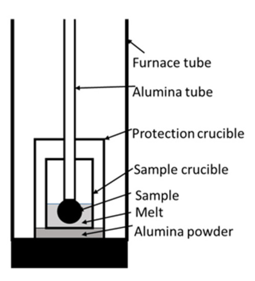
Figure 1. Test setup of the high-temperature tube furnace.
Table 1. Characteristics of the test setup components.
| Component | Dimensions/mm | Material | Comment |
|---|---|---|---|
| Protection Crucible * | Ø117.6 × Ø108.6 × 180 | Al2O3 | |
| MgO Sample Crucible * | Ø48.5 × Ø36.0 × 10⁵ | MgO | for EAF slag test |
| Alumina Sample Crucible * | Ø49.5 × Ø42.6 × 68.7 | Al2O3 | for ULC, HM, and SAF slag tests |
| Wire | Ø1 | Mo | |
| Screw | “Spax” 2.5 × 12 | steel | |
| Furnace Chamber | Ø180 | Al2O3 |
A manually operated pneumatic cylinder controlled the dipping process during the test. Every trial was filmed to evaluate the exact immersion time. After discharging, the sample was quenched via liquid nitrogen to avoid extensive reoxidation. Per each melt, three samples were immersed; after the third test, the melt temperature was measured with Heraeus Type S thermocouples (Heraeus, Hanau, Germany).
Before the metallographic preparation, we took photographs of each sample using a Sony Alpha 6000 DSLM camera (Sony Group Corporation, Tokyo, Japan). Afterward, the specimens were cold-embedded, halved, ground, and polished. The microsections were investigated using a Keyence VHX 7000 digital microscope (Keyence Corporation, Osaka, Japan).
2.2. Materials
Typical BF-grade iron ore pellets were used; their composition is shown in Table 2. Samples of appr. 500 g ore were prepared using a vertical reduction furnace (VRF), precisely described in. After preheating under nitrogen purging with 20 Nl/min, the reduction was performed at 900 °C with 25 Nl/min pure H2. The furnace has a scale that allows monitoring the weight loss during reduction. The process was stopped after reaching a metallization degree of approximately 90%. The carbon-free DRI sample is called “0%C” in the following chapters.
Table 2. Composition of the unreduced ore pellets in wt.%.
| Fetot | Fe2O3 | FeO | CaO | SiO2 | Al2O3 | MgO |
|---|---|---|---|---|---|---|
| 64.9 | 92.5 | 0.37 | 0.48 | 4.55 | 0.84 | 0.45 |
To carburize some carbon-free DRI with Methane, approx. 130 g was recharged into the VRF and treated with 4 Nl/min CH4. Table 3 lists the carburizing temperatures and times, the contents of C and metallic, divalent, and trivalent iron (Femet, Fe2+, Fe3+), and the metallization degree (MD). The contents of the Fe species (Fetot, Femet, Fe2+) were analyzed using titration methods, and the total carbon content was analyzed by LECO (LECO Corporation, St. Joseph, MI, USA), without focusing on its bonding state. An industry partner delivered the Hot Briquetted Iron (HBI) sample, whose chemical composition is shown in Table 3.
Table 3. Carburizing conditions and composition of the DRI and HBI samples/species in wt.%.
| Sample | TCarb/°C | tCarb/min | Femet | Fe2+ | Fe3+ | Ctot | MD/% |
|---|---|---|---|---|---|---|---|
| C750 | 750 | 20 | 81.35 | 5.01 | 0.01 | 1.79 | 94.2 |
| C800 | 800 | 25 | 82.46 | 2.82 | 0.00 | 3.71 | 96.7 |
| HBI | - | - | 84.6 | 4.1 | 2.3 | 2.00 | 93.0 |
Ultra-low carbon (ULC) steel was used to simulate low-carbon crude steel conditions in the EAF; the samples for the melting tests were cut from a continuous casting slab provided by an industrial partner. Table 4 lists its chemical composition, analyzed by optical emission spectroscopy (OES).
Table 4. ULC composition/wt.%.
| C | Si | Mn | Al | Ti | S | P | Ni | Cu | Cr |
|---|---|---|---|---|---|---|---|---|---|
| 0.007 | <0.001 | 0.146 | 0.028 | 0.079 | 0.015 | 0.009 | 0.011 | 0.005 | 0.027 |
For the hot metal (HM) tests, desulphurized HM chips with a diameter of 34 mm and a width of 9.4 mm were used. Table 5 summarizes the HM composition analyzed with OES.
Table 5. HM composition/wt.%.
| C | Si | Mn | S | P |
|---|---|---|---|---|
| 4.6 | 0.4 | 0.6 | 0.004 | 0.07 |
The slags were synthetically prepared from pure oxides and premelted in an “Indutherm MU700” induction furnace (Indutherm Erwärmungsanlagen, Walzbachtal, Germany). The liquids were cast onto steel plates for rapid cooling before being used for the immersion tests. Table 6 and Table 7 report the slag compositions. The slags were dissolved in Li tetraborate and analyzed with inductively coupled plasma optical emission spectroscopy (ICP-OES).
Table 6. SAF-like slag composition in wt.%; all values were measured as elements and converted to oxides.
| Before Test | After Test | |
|---|---|---|
| CaO | 40.1 | 39.4 |
| SiO2 | 39.8 | 39.1 |
| Al2O3 | 11.3 | 12.9 |
| MgO | 8.02 | 7.80 |
| Fe | 0.62 | 0.62 |
| B2 = CaO/SiO2 | 1.01 | 1.01 |
Table 7. EAF-like slag composition in wt.%; all values were measured as elements and converted to oxides.
| Before Test | After Test | |
|---|---|---|
| CaO | 27.2 | 18.8 |
| SiO2 | 21.2 | 13.4 |
| Al2O3 | 8.20 | 9.73 |
| MgO | 9.88 | 31.2 |
| Fe | 26.1 | 20.9 |
| B2 = CaO/SiO2 | 1.28 | 1.40 |
2.3. Immersion Test Program
As mentioned above, two DRI process routes are possible in the future, which means the DRI production will be combined with either EAF or SAF. With this in mind, a test program was established for the following aspects of DRI melting:
Influence of C content in DRI (carbon-free, hydrogen-based DRI was compared to carburized DRI, which approximates natural gas-based DRI)
Composition of the liquid metal (low and high C content)
Composition of the slag (EAF and SAF slag)
Density of the DRI samples (DRI vs. HBI)
Table 8 sums up the executed tests with their parameters. The nomination of the sample number contains the DRI type (0%C, C750, C800, and HBI) as well as the specific melt (ULC, HM, EAF-[slag], SAF-[slag]); Tmelt is the measured temperature of the melt after the tests. In the experiments with EAF slag, temperature measurement was impossible since an MgO crucible was used, whose inner diameter was too small to insert the thermocouple.
Table 8. List of the samples.
| Sample Number | Liq. Medium | tImmersion/s | Tfurnace/°C | Tmelt/°C |
|---|---|---|---|---|
| C750-ULC-1 * | ULC | 4 | 1625 | - |
| C750-ULC-2 | 3 | 1544 | ||
| C750-ULC-3 | 4 | 1555 | ||
| C800-ULC-1 * | 4 | - | ||
| C800-ULC-2 * | 3 | - | ||
| C800-ULC-3 | 3 | 1555 | ||
| C800-ULC-4 | 4 | 1555 | ||
| 0%C-ULC-1 | 4 | 1544 | ||
| 0%C-ULC-2 | 3 | 1544 | ||
| 0%C-ULC-3-10s | 10 | 1558 | ||
| HBI-ULC-1 | 3 | 1558 | ||
| HBI-ULC-2 | 3 | 1558 | ||
| 0%C-HM-1 | HM | 4 | 1500 | 1390 |
| 0%C-HM-2 | 3 | |||
| HBI-HM-1 | 3 | |||
| 0%C-SAF-1 | SAF slag | 3 | 1550 | 1479 |
| 0%C-SAF-2 | 3 | |||
| C800-SAF-1 | 3 | |||
| 0%C-EAF-1 x | EAF slag | 3 | 1600 | - |
| 0%C-EAF-2 x | 3 | |||
| C800-EAF-3 x | 3 |
The samples C750-ULC-1, C800-ULC-1 and C800-ULC-2 were used as pre-tests and cooled with gaseous nitrogen. They were not further examined. The immersion time was usually 3–4 s, except for the sample 0%C-ULC-10s-3, for which it was set to 10 s to analyze the melting progression of carbon-free DRI. The accuracy was about 1 s because the pneumatic cylinder was manually controlled. The EAF slag was liquefied in an MgO crucible; all the other tests were performed in an Al2O3 crucible, as shown in Table 1.

