Investigations on the Interaction Behavior between Direct Reduced Iron and Various Melts (2)
3. Results
During the experiments, a few aspects were noticeable, as reported below.
In some tests with the carburized samples, sparks and splashes could be observed. This could be due to the chemical reaction between C and FeO, which generates CO gas. This phenomenon was most pronounced when DRI or HBI was immersed in hot metal.
In all tests with hot metal (0%C-HM-1, 0%C-HM-2, and HBI-HM-1), the samples were melted entirely after a 3–4 s dipping time. As a consequence, no more investigations were possible. A further reduction of the immersion time was not manageable, since the actuator for controlling the pneumatic cylinder movement was at its limit. Another noteworthy point is the remarkable temperature difference between the furnace and the melt during the hot metal tests. The endothermic reduction reactions of FeO with C during the immersion of the samples are the most likely explanation for this phenomenon.
After the tests, the samples were evaluated visually. The following was noticeable about the images.
• The 0%C samples in Figure 2 showed smooth surfaces for steel and slags. This indicates that no chemical reactions took place between DRI and the liquids. After an increased immersion time, see sample 0%C-ULC-10s-3 in Figure 3, the optical impression of the surface was less shiny and appeared matte.
• As the DRI carbon content increased, a reduction of the remaining iron oxide seemed to happen. Consequently, the surface became more fissured with increasing carbon levels (compare Figure 2a with Figure 4 and Figure 5a). Frozen gas bubbles on the adhering melt residues indicated gas formation.
• When a highly carburized DRI-pellet was immersed in a slag containing iron oxide, a reaction of C from the sample with FeO in the slag might have occurred (see sample C800-EAF-1 in Figure 5c).
• When immersed in the SAF slag, no reactions were expected, as the temperature was much lower. The poorer slag adhesion at C800-SAF, shown in Figure 5b, indicates less wetting than for the carbon-free sample 0%C-SAF, visible in Figure 2b. This observation is consistent with slag wetting on carbon-containing refractory material. Comparing the shell shapes of 0%C-ULC-1 and C750-ULC-2 in Figure 2a and Figure 4, respectively, the former was more or less droplet-shaped, while the latter had a plain surface on the bottom. This flat lower area is also visible in C800-ULC-4 and C800-EAF, as implied in Figure 5a,c. One explanation could be that the melt on the surface of the carburized pellets had a lower viscosity than the almost carbon-free ULC melt.
• Despite the significant carbon content of 2 wt.%, HBI showed a similar, smooth, glossy surface as 0%C-DRI (see Figure 6).
Replicated tests are not illustrated, considering the results were qualitatively reproducible. As described above, the samples dipped in hot metal were completely melted during immersion. Thus, no further analysis was possible. This rapid dissolution indicates a different melting mechanism, as the theoretical melting point of pure iron is approx. 1538 °C. The liquidus temperature was calculated using Factsage 8.0 and the FactPS database and was much higher than the HM temperature, as shown in Table 8. This effect seems analogous to diffusive scrap melting, which was extensively investigated by Penz et al.. Carbon diffused from liquid hot metal to the solid iron phase at the liquid–solid interface, with heat being transported in the same direction. The high carbon content in the solid lowered its liquidus temperature and caused its further melting.
Figure 2. Macroscopic photographs of selected 0%C samples: (a) 0%C-ULC-1; (b) 0%C-SAF-1; (c) 0%C-EAF-2.

Figure 3. Macroscopic photograph of the sample 0%C-ULC-10s-3.

Figure 4. Macroscopic photograph of the sample C750-ULC-3.

Figure 5. Macroscopic photographs of selected C800 samples: (a) C800-ULC-4; (b) C800-SAF-1; (c) C800-EAF-1.

Figure 6. Macroscopic photograph of the sample HBI-ULC-2.
Digital microscope images are shown in Figure 7 and Figure 8 below. The sections of 0%C-ULC-1 and 0%C-ULC-10s-3 with 4 and 10 s immersion time demonstrate that the pellet melted as heat transport from the surface to the core progressed (compare Figure 7a,b). Comparing the 0%C-ULC samples with C750-ULC-2 and C800-ULC-4 in Figure 9, carburized DRI appeared to liquefy much faster, since the higher carbon content lowered the liquidus temperature .
Figure 7. Digital microscope images of (a) 0%C-ULC-1; (b) 0%C-ULC-10s-3, dipped into liquid ULC steel.
Figure 8. Digital microscope images of (a) 0%C-SAF-2; (b) 0%C-EAF-2, dipped into EAF/SAF slag.
Figure 9. Digital microscope images of (a) C750-ULC-2; (b) C800-ULC-4, both dipped into liquid ULC steel.
Comparing the samples immersed in slag, shown in Figure 8 and Figure 10, the results are consistent with the photographs in Figure 2b,c and Figure 5b,c. A slag layer coated the DRI surfaces; the absence of bubbles indicated that no reactions occurred when carbon-free DRI was immersed. On the other hand, carburized DRI formed a less adherent slag layer with the iron oxide-free SAF slag and was highly reactive with the iron oxide-containing EAF slag. The former phenomenon could be explained by the poor adhesion of the glassy slag layer. The latter was due to the rough surface of C800-EAF, visible in both the photograph and the digital microscope image in Figure 5 and Figure 10. Table 6 and Table 7 reports the slag composition before and after the experiments.
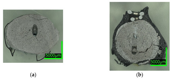
Figure 10. Digital microscope images of (a) C800-SAF-1; (b) C800-EAF-1, dipped into slag.
HBI shows a behavior similar to zero-carbon DRI, suggesting that the higher density of briquetted material compared to that of unbriquetted material had a greater influence on the dissolution behavior than the carbon content in HBI. This typically ranges between 0.5 and 1.6% [57,58] or even 2% as in the present case (compare Figure 2 and Figure 7 with Figure 6 and Figure 11).

Figure 11. Digital microscope images of the HBI-ULC-2-1 sample, dipped into ULC.
Heat Transfer Conditions
For comparing the slag and the ULC immersion tests, differences in the heat transfer conditions should be considered. While the slag temperature in the C800-SAF test was 1479 °C, the liquidus temperature of iron with 3.79% carbon was approx. 1213 °C, calculated by FactSageTM 8.0 using FSStel Database. This resulted in a significant superheating of 266 °C. As in Figure 8 no melting of the pellet can be noticed, the heat transfer could be limited when DRI became in contact with the non-reactive slag. In the scope of a similar study, Sadrnezhaad and Eliot described a solid adherent slag layer. Using inert nickel spheres, the authors measured a maximum layer thickness between approximately 1.5 and 2.5 mm. A similar effect was described by Pineda-Martìnez et al. by modeling the heat transfer and comparing it to literature data.
The Prandtl (Pr) numbers were calculated to characterize the slag and the ULC melt conditions. Pr, shown in Equation (1), describes the ratio between the velocity boundary layer and the temperature boundary layer, calculated by the kinematic viscosity ν/(m2/s) and the thermal diffusivity a/(m2/s). Transforming both components, Pr can be written as a function of the kinematic viscosity η/(Pas), the heat capacity of the fluid cp/(J/Kmol), and λFl.

Table 9 lists the calculated values and the used parameters for the previously mentioned Prandtl number for both cases, slag–DRI and liquid iron (ULC)–DRI. It shall be noted that some literature data vary broadly. Nevertheless, the results indicate the order of magnitude. The lower thermal conductivity and the higher viscosity of liquid slag, compared to liquid iron, result in a Prandtl number which is increased by a factor of 1000 (176 vs. 0.111). Consequently, when in contact with slag, the temperature boundary layer, an indicator for thermal diffusion, is relatively thin compared to the velocity boundary layer, representing impulsive transport. This difference may be a reason for the unmelted carburized DRI, despite the relatively high superheating.
Table 9. Calculated dimensionless Prandtl numbers, incl. literature data for the parameters.
| Parameter | Value | Comment | Source |
|---|---|---|---|
| cpFe,liq | 820 J/kgK | [48] | |
| λFe,liq | 37.65 W/mK | [48] | |
| ηFe,liq | 5.08 mPas | at 1550 °C | [56] |
| cpslag | 696–1171 J/kgK | 696 used for calculation | [48,61] |
| λslag | 1.1715–1.3589 W/mK | 1.2625 used for calculation | [48] |
| ηslag | 0.320 Pas | calculated with FactsageTM for 1479 °C | |
| PrFe-DRI | 0.111 | ||
| PrSlag-DRI | 176 |
4. Discussion
ULC experiments: The results of dipping 0%C samples and HBI into a low carbon melt indicated that heat transfer was the driving force in this case. The 0%C-ULC-3 specimen in Figure 7b confirmed this, since it showed the growth of a liquefied shell. The higher the carbon content, the thicker the shell at similar dipping times. The lower liquidus temperature explained the faster melting in iron–carbon mixtures. In principle, the observations agree with the calculated results of González et al., i.e., an increasing sample diameter immediately after immersion, followed by the melting of this surface layer. However, the melting time strongly depend on parameters such as DRI porosity, initial diameter, or gangue content. Therefore, it was difficult to make quantitative comparisons. Additionally, the high-carbon samples in Figure 4 and Figure 5 had a rough surface with many bubbles due to the reduction of some residual iron oxide with carbon. These reactions, along with the resulting blisters, may benefit the EAF process. Various authors reported benefits in terms of lower electrical energy consumption, less nitrogen content, or better slag foaming.
Hot Metal experiments: The DRI and HBI samples were fully melted after 3–4 s of immersion in the hot metal. At first sight, this was not expected, as the liquidus temperature of pure iron (approx. 1538 °C, according to FactSageTM 8.0 and the FactPS database) was higher than the hot metal temperature. Further, this differs from the results for ULC steel. Penz et al. investigated the dissolution of scrap in hot metal, which is a similar process, and described the following melting steps:
• Initial formation of a solid hot metal layer, which liquefied again after the heat transport provided enough overheat
• Diffusive melting meant a mass transfer from carbon-rich hot metal to low-carbon-containing solid steel
• Heat transfer was the primary mechanism if the carbon content of both phases was balanced or the scrap temperature exceeded its liquidus temperature
Slag experiments: No reactions occurred, since no iron oxide was available in contact with SAF slag. The high C sample C800 was conspicuous in two respects: first, the slag layer adhered only loosely, indicating less wetting than on the 0%C-sample; second, the entire pellet appeared unmelted, which was unexpected, as the melting temperature of the carburized iron was 266 °C below the slag temperature. In comparison, the ULC melt of the test C750-ULC-3 was approx. 143.5 °C (TULC = 1544 °C; Tliq = 1400.5 °C, acc. to FactSageTM 8.0, FactPS, FSStel databases) overheated and was liquefied in the near-surface region. Therefore, the Prandtl number was calculated for both ULC and slag cases. In the latter case, it was approx. 1000 times higher, indicating different heat transition conditions. This observation was in qualitative agreement with the numerically calculated results of González et al. and Pineda-Martínez et al., who reported significantly longer melting times in contact with slag.
In contrast, the high-C sample appeared to be very reactive in contact with the EAF slag, which contained high levels of iron oxide. The core of the DRI pellet, see the microscope image in Figure 10b, was almost unmelted, consistent with C800-SAF and indicative of lower heat transfer when in contact with a slag. Nevertheless, bubble formation due to the reaction between carbon and iron oxide could have led to higher turbulence in the surface boundary layer and thus an increased heat transition.
5. Conclusions
A vertical furnace was used to investigate the behavior of sponge iron in contact with liquids. High, medium, and carbon-free-DRI, as well as HBI, were immersed into melts of ULC, hot metal, and slags. Based on metallographic examinations, processes occurring in different cases were characterized. Carbon, either in the sponge iron or in the melt, increased the melting rate due to its effect on the liquidus temperature of iron. Further, reduction reactions of iron oxides, either in the DRI pellet or in the high-FeO slag, could be observed, as indicated by the occurrence of gas bubbles on the surfaces of these samples. Even the high-carbon DRI sample remained unmelted when in contact with iron oxide-free slag. This indicated different heat transfer conditions between liquid slag and steel, which was confirmed by calculating the Prandtl numbers. While HBI also showed a rapid dissolution in hot metal, the behavior in a low-carbon melt was the same as for 0%C-DRI, that of sponge iron without carbon. Therefore, particle density was also a crucial parameter in the melting behavior.
Pfeiffer, A., Wimmer, G., & Schenk, J. Investigations on the Interaction Behavior between Direct Reduced Iron and Various Melts. Materials, 15(16), 5691. https://doi.org/10.3390/ma15165691