Pressurized Chemical Looping for Direct Reduced Iron Production: Economics of Carbon Neutral Process Configurations (1)
1. Introduction
1.1. Background
Globally, the 1.9 Gtonnes per year of iron and steel produced results in 2.6 Gtonnes of CO2 emissions. One such way of achieving those emissions reduction targets is to replace the blast furnace and basic oxygen furnace (BF-BOF) in the integrated steel mill with direct reduced iron (DRI) production followed by an electric arc furnace (EAF). This transition can reduce the emissions from steelmaking by up to 68%. The DRI plant is one of the remaining large point source contributors to CO2 emissions from iron and steelmaking, since the heat for the process is conventionally supplied via the combustion of fossil fuels.
Midrex is the technology provider that currently possesses the largest market share of operational DRI plants globally. For this reason, the process configurations in this work are considered as modifications to, and are compared against, the standard Midrex process. The means of achieving carbon neutrality are limited to carbon capture in the scope of this work, though other researchers are considering other routes to eliminate CO2 emissions.
Chemical looping is an energy conversion technology that inherently separates CO2 from flue gas upon the combustion of a fuel, without the need for an air separation unit, for easy and efficient carbon capture. Unlike amine-based CO2 capture, which requires additional large equipment be installed to separate CO2 from the flue gas, chemical looping reactors directly replace the units used to supply process heat. When performed at elevated pressures, it is referred to as pressurized chemical looping (PCL). The pressurization of chemical looping has many advantages, including reduced equipment size and plant footprint, reduced capital cost, increased reaction rates, increased heat transfer rates, and enhanced latent heat recovery. In one variant using fluidized beds, chemical looping requires two reactors (air and fuel), which are typically housed in separate process vessels. The bed material transferred between the reactors is an oxygen carrier comprised of metals at different oxidation states. In the air reactor, air is used as the fluidizing gas. The oxygen carrier is oxidized, releasing heat that is used to achieve the desired objective (reforming, steam production, etc.). The oxygen-depleted air (herein referred to as “vitiated air”) is vented without CO2 emissions. The oxidized oxygen carrier is then passed to the fuel reactor, where, provided there is sufficient oxygen, it reacts with the fuel to produce CO2 and water via a solid state or homogenous reaction. After the cooling and conditioning of the flue gas to remove the majority of the water, the captured CO2 stream is sent to a compression and drying unit to prepare it for transportation and storage or utilization.
In this work, the economics of applying PCL technology within a Midrex-type DRI plant are investigated in comparison to the original Midrex process, as well as in comparison to existing commercially available post-combustion carbon capture technology.
1.2. Process Description
Three process configurations were explored: a base case that consists of a standard Midrex DRI configuration, the application of amine absorption to the flue gas from the base case (Base Case + PCC) to achieve 95% capture, and the integration of PCL to replace the reformer of the Midrex process while simultaneously capturing CO2 (PCL-DRI). The latter two cases are nearly carbon neutral (hereafter denoted as carbon neutral for brevity), while all CO2 from the base case is vented to the stack.
1.2.1. Base Case
The configuration and performance of the base case Midrex process has already been discussed in detail in previous work, where it was denoted as Base-M. Figure 1 shows the major equipment in this process, which consists of a shaft furnace, a reformer, and supporting equipment for the treatment of the recycled top gas and the preheating of feed gases. The inputs to the shaft furnace are the iron ore, provided as DRI-grade pellets, and a hot reducing gas consisting of a mixture of CO, H2, CH4, CO2, H2O, and N2. Through contact with this gas, the majority of the iron in the pellets is reduced to metallic iron, with a lesser fraction remaining as FeO. Downstream processing in the EAF melts down and refines this product into steel. Cooling gas at the cone of the furnace controls the final product temperature. The size, cost, and performance of the shaft furnace is kept constant across all configurations studied in this work.
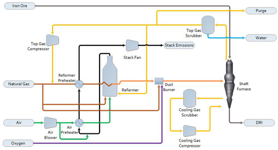
Figure 1. Midrex base case process flow diagram.
The reformer is fed natural gas and recycled top gas and produces the syngas used as the reducing gas in the shaft furnace after additional heating in a duct burner. Dry reforming reactions dominate in the Midrex reformer. The syngas outlet temperature (925 °C), pressure (220 kPa(a)), and composition are kept constant across all configurations. The flue gas from the reformer firebox is the source of all the CO2 emissions from this process.
Though not shown in Figure 1 for simplicity, solids handling equipment for the iron ore feed to the shaft furnace are also included in the scope of the plant costs evaluated here. This equipment consists of a storage silo, bucket elevator, surge bin, swing hopper, and injection hopper.
1.2.2. Base Case with Post-Combustion Capture (Base Case + PCC)
For this configuration, the base case plant shown in Figure 1 is identical, apart from the removal of the stack fan. The flue gas stream from the reformer firebox is directed to the equipment shown in Figure 2. First, it passes through a flue gas cooler and blower, and then it is further cooled and conditioned in a direct contact cooler (DCC). Heat is removed from the DCC’s recirculating water using cooling water in a compact heat exchanger. The removal of the CO2 from the flue gas is achieved in a packed column absorption tower using MEA as the solvent. The depleted flue gas stream, consisting primarily of N2, is scrubbed of residual amine in a wash water column before being vented to the atmosphere. The CO2-rich solvent is heated in the cross-heat exchanger and sent to the regeneration column, where it is heated to extract the CO2 as a pure, low-pressure stream from the top of the column. Substantial steam input is required to the reboiler of the regenerator to achieve this separation.

Figure 2. Process flow diagram of flue gas cooling, conditioning, and amine absorption.
The low-pressure CO2 product from the amine system is sent to a standard CO2 compression and drying package, as shown in Figure 3. The CO2 compressor has six stages, with intercooling. Water knockout after the first two compression stages followed by a dryer removes moisture to meet the specification for the Alberta Carbon Trunk Line.

Figure 3. Process flow diagram of the CO2 compression and drying package.
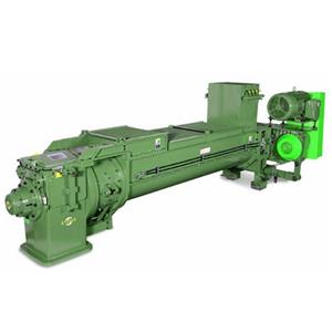
1.2.3. Pressurized Chemical Looping DRI (PCL-DRI) The configuration and performance of a Midrex DRI plant integrated with PCL has already been discussed in detail in previous work, where it was denoted as PCL-DRI-M. In this configuration, the reformer firebox is replaced with parallel PCL reactors. As a modification to the previous work, external fluidized bed heat exchangers are added here in sequence with the air reactors to provide a sufficient heat transfer area, as shown in Figure 4. The reformer tubes are placed in the bed portion of the air reactor, where most of the heat from combustion is released, and in the beds of the connected fluidized bed heat exchangers. Equipment is added to recover heat and remove entrained solids from the concentrated flue gas and vitiated air flowing from the fuel and air reactors, respectively. Considering the flue gas exiting the fuel reactor, bulk solid removal is achieved with cyclones. The remainder of the fine particulate matter is removed using a DCC. The cooled flue gas is then sent to the second stage of the CO2 compression and drying package shown in Figure 3. Considering the vitiated air exiting the air reactor, the temperature of the vitiated air exiting the fluidized bed heat exchanger is reduced significantly through the heat removal to the reformer tubes, allowing the majority of solids to disengage before they exit the vessel, since the up-flowing gas velocity in the reactor drops below the transport velocity of the solids. The remainder of the particulate matter is removed via a candle filter before the gas is sent to a turbine for power recovery to help drive the main air compressors. Not shown in Figure 4 for simplicity, but included within the assessment, are the solid storage and handling equipment for both charging the shaft furnace with the pelletized iron ore feed (DR pellets) and performing oxygen carrier makeup to the PCL reactors.

Figure 4. Process flow diagram for PCL-DRI.
The traditional arrangement of a chemical looping reactor consists of two separate process vessels: one housing the air reactor and one housing the fuel reactor. Solids are transferred between the vessels using external solids transfer legs and non-mechanical seals, such as loop seals. This type of arrangement often has challenges in reliability due to the external solids transfer legs, especially at elevated pressures, and requires a larger footprint. To overcome these challenges, in this work, the reactor design is inspired by Chalmers University’s 300 W chemical looping test unit, incorporating both reactors into a single vessel. Chalmers’ reactor operated at near-atmospheric pressure, while the authors here adapt the design for pressurized operation, using ilmenite as the oxygen carrier. Ilmenite, consisting ideally of FeTiO3 (FeO·TiO2), is a naturally occurring ore that is readily available at low cost. It is used directly after crushing; unlike with the feed to the shaft furnace, pelletization is not required. This reactor, shown in Figure 5, operates with the fuel reactor in bubbling mode, fluidized by the recycled top gas from the shaft furnace that is used as fuel. Due to efficiency gains from the enhanced heat transfer in fluidized beds compared to radiant heat transfer in traditional reformer furnaces, the reactors are able to operate at a lower temperature than the Midrex reformer and thus require less fuel input to the fuel reactor. The reduced oxygen carrier is transferred from the fuel reactor to the adjacent air reactor through an internal loop seal that sits beneath both beds. The air reactor is fluidized with air and operates as a circulating fluidized bed. The oxidized oxygen carrier is transported to the top of the reactor, to a disengagement zone, which causes the solids to drop down into the upper loop seal. Passage through this loop seal returns the oxygen carrier back to the fuel reactor, completing the loop. For PCL-DRI, both loop seals are fluidized with steam generated using waste heat from the hot flue gases, and the reformer tubes are inserted into the bed of the air reactor.

Figure 5. PCL-DRI reactor schematic showing (A) the cut view and (B) the plan view.
This compact reactor design, detailed in Table 1, was selected to reduce the capital costs, minimize the footprint, and improve the operability and reliability of the PCL system. A size constraint of 8 m in diameter was used for the PCL reactor vessel to ensure the practicality of fabrication, transportation, and mechanical support of the vessel; identical parallel trains allow the system to be scaled up to any capacity in a modular fashion. The operating pressure was selected based on the optimal range of 500–800 kPa(a) identified when applying PCL to a different application. The upper limit of this range was used to enhance heat transfer. The operating conditions of the PCL reactors in this case were updated after the previous work to address challenges relating to fitting the reformer tube bundles in the reactor. At an air reactor temperature of 950 °C, the required surface area of the reformer tubes was too large to reasonably fit within the available reactor volume. The air and fuel reactor operating temperatures have been increased to 1050 °C for this work, which is the upper limit for fluidized bed operations with ilmenite ore to avoid sintering or agglomeration. The reformer heat transfer area per reactor was determined using tubes with a 0.12 m outer diameter and a pitch of 0.25 m. To accommodate the required size of the reformer, two external fluidized bed heat exchangers were employed alongside the four parallel PCL reactor systems to expand the effective size of the air reactor. The sizing of these external fluidized bed heat exchangers is given in Table 2.
Table 1. PCL reactor design properties for PCL-DRI.
| Oxygen Carrier Properties | Units | Value | |
|---|---|---|---|
| Material | - | Ilmenite ore | |
| Average particle diameter (dsv) | µm | 350 | |
| Particle density | kg/m3 | 4700 | |
| Bed inventory (per PCL reactor) | tonnes | 965 | |
| PCL Reactor Geometry | Units | Value | |
| Pressure vessel height | m | 10 | |
| Pressure vessel outer diameter | m | 7.2 | |
| Refractory thickness | m | 0.20 | |
| No. parallel reactors | - | 4 | |
| Reformer tube area per reactor | m2 | 610 | |
| PCL Reactor Fluidization Parameters | Units | Air reactor | Fuel reactor |
| Bed temperature | °C | 1050 | 1050 |
| Freeboard pressure | kPa(g) | 700 | 700 |
| Cross-sectional area at bottom of bed | m2 | 22.4 | 11.9 |
| umf—bottom of bed (Chitester et al. (1984) [29]) | m/s | 0.08 | 0.12 |
| Gas velocity—bottom of bed | m/s | 0.23 | 0.34 |
| Gas velocity—riser | m/s | 3.9 | 0.34 |
Table 2. External fluidized bed heat exchanger design properties for PCL-DRI.
| Parameter | Units | Value |
|---|---|---|
| Orientation | - | Horizontal |
| Pressure vessel length | m | 19 |
| Pressure vessel outer diameter | m | 8.2 |
| Refractory thickness | m | 0.20 |
| No. parallel units | - | 2 |
| Reformer tube area per unit | m2 | 1280 |
| Bed inventory per unit | tonnes | 435 |