The Behavior of Direct Reduced Iron in the Electric Arc Furnace Hotspot (1)
1. Introduction
Electric arc furnaces (EAF) produced more than 500 million t of crude steel in 2021. Although scrap is the primary iron carrier, the EAF is also a suitable aggregate for processing direct reduced iron (DRI) or hot briquetted iron (HBI). This combination of direct reduction reactor (DR) and EAF can be considered the major ore-based steelmaking strategy in natural gas (NG)-rich countries such as Mexico, Saudi Arabia, and United Arabic Emirates. Nowadays, the 119 Mt DRI production in 2021 is just a minor share of the total ferrous feed for global steel production. However, due to the ambitious climate targets of the European Union, this technology may gain greater importance in the future. Therefore, the processing behavior of sponge iron is also of significant interest.
Many authors investigated the DRI melting behavior in the past. From the perspective of a single pellet, one must distinguish between the dissolution in liquid steel, hot metal, and slags. González et al. mathematically describe the initial formation of a solid superficial layer on the pellet in contact with liquid iron. The layer increases the particle diameter from 12 to 18 mm, which starts to soften after approximately 6 s. Depending on the considered EAF arc length, the calculated diameter reaches 0 mm after 13 to 17 s. The melting rate critically depends on the initial pellet diameter. Pineda-Martínez et al. report similar results in contact with non-reactive slags. However, due to the lower heat transfer, the melting times are dramatically higher compared to the liquid steel case. Besides the particle size, bath stirring is a decisive factor, as forced convection critically increases heat transport. Ramirez-Argaez et al.further use CFD modeling to study the multiphase slag–steel–DRI system, with similar results. Pfeiffer et al.confirm this trend experimentally. They submerge single samples of DRI and HBI into a liquid pool and quench the specimen after predefined times. Carbon-free DRI initially acquires solid layers from steel as well as slags. However, the higher the DRI carbon content, the faster the pellet liquefies in steel. Nevertheless, even highly carburized sponge iron remains solid in slag after three seconds of dipping. The authors explain this difference analytically using the Prandtl number, which is increased by a factor of approximately 1000 in the slag case. Samples dipped into saturated hot metal melt much faster, even if the melt temperature is below the iron liquidus temperature. Carbon diffusion from the liquid to the solid phase explains that. Penz et al. investigate this phenomenon for scrap melting in basic oxygen furnace (BOF) conditions. After forming the initial solid shell, carbon diffuses as long as the liquidus temperature falls below the melting point. Once that happens, melting progresses.
DRI is usually continuously charged through the fifth hole in the EAF cover. To gain consistent flat bath operation, DRI-based EAF are practiced with up to 30% hot heel. This operation is characterized by a short and stable arc mode and a smoothly increasing bath level. The ideal charging point is located in the hot spot, in the center of the three AC-EAF electrodes. Depending on the DRI temperature and the melting capacity, charging rates are limited to avoid the formation of so-called “icebergs” or “ferrobergs”. Typical values range from 34 kg/(min∙MW) for cold DRI up to 55 kg/(min∙MW) for hot DRI. Consequently, hot DRI feeding is beneficial not only in terms of energy consumption, but also in terms of the charging rate. Therefore, lower tap-to-tap times can be expected.
In recent years, a lot of research has been conducted with a focus on electric steelmaking. The most important topics in this case are slag operation, process modelling, and application of alternative carbon sources. These topics are of decisive importance when it comes to optimizing the EAF process for CO2-neutral steelmaking in the future. Slag operation defines the process sequence in multiple aspects. On the one hand, slag foaming covers the electric arc and avoids radiation losses. Furthermore, it defines the yield of metallic iron since it is high in (FeO), the partition of harmful elements such as phosphorus, and the refractory lifetime. The use of biomass-based carbon carriers provides the chance to almost fully reduce fossil-based carbon emissions, as the electric arc furnace relies on a minimum amount of carbon for slag foaming operation. Lastly, process simulation and modelling enhance process efficiency. The better one’s ability to simulate the EAF and its mass and energy balances, the more energy and input materials, such as slag forming oxides, can be saved.
However, there is still little data available in two respects. First is the application of DRI based on hydrogen. This kind of sponge iron is free of carbon. Therefore, its liquidus temperature is significantly higher than that of the conventional one. This difference may lead to a different behavior during the melting step in the EAF. Second is the direct observation of the feed material in the electric arc; it would be of great interest to learn more about its behavior. This study aims to generate deeper understanding in both mentioned respects and analyzes the behavior of DRI in an electric arc. Next to hydrogen-based carbon-free material, carburized samples and a continuous slag feed are tested. The observations provide more profound knowledge about the melting procedure and can be used to explain the optimal DRI charging strategy and deliver an idea about the final crude steel quality.
2. Materials and Methods
Table 1 lists the applied iron ores and their composition. An industry partner provided the samples and the chemical compositions. DR-grade pellets were used in tests 0, 1, and 2; a similar fine ore to test DRI fines from fluidized bed reduction was used in Test 3. To make the result of the slag Test 4 clearer, a BF-grade pellet with a higher gangue content was tested.
Table 1.Ore compositions in wt.-%.
| 2 Fetot | Fe2+ | SiO2 | Al2O3 | CaO | MgO | TiO2 | MnO | Size/mm | Test No. | |
| DR-Pellet | 67.5 | 0.19 | 1.94 | 0.32 | 0.87 | 0.35 | 0.06 | 0.21 | 10–12.5 | 0, 1, 2 |
| BF-Pellet | 64.8 | 0.42 | 5.79 | 0.47 | 0.48 | 0.6 | 0.06 | 0.04 | 12.5–16 | 4 |
| Fine-raw | 66.8 | 6.19 | D50 = 0.1 | - | ||||||
| Fine-oxi 1 | 66.4 | 1.87 | D50 = 0.1 | 3 | ||||||
| 1 Composition of oxidized fine ore was determined by the mass balance; 2 Fetot—Total iron content. | ||||||||||
The pellet samples were reduced in a vertical reduction furnace (VRF) using a 75 mm diameter retort, precisely described in [30,31]. This is a standard aggregate used, for example, to perform standard tests such as ISO11258. The retort is fixed on a scale, providing the possibility to monitor the weight loss during the test. The reduction gas is preheated in the furnace chamber; it enters the retort from the bottom and exits through the top into the off-gas duct. The thermocouple measures the temperature in the center of the pellet load. Approximately 500 g pellets were charged. After heating up to 900 °C under nitrogen purging, 25 NL/min pure H2 was applied. Once the mass loss reached the demanded metallization degree (MD), the test was stopped, and the material was cooled under a nitrogen atmosphere. Three pellet samples were prepared: two from the DR-pellets were reduced to 90% and 94% MD; one from the BF-pellets was reduced to 90% MD. In the same retort, the highly reduced DR-grade DRI was carburized afterward under 8 NL/min CH4 at 800 °C. According to the mass balance, it contains 2.1% carbon; due to the high initial reduction, this is considered a reasonable presumption.
The fine ore was preoxidized in a heat treatment furnace for 8 h at 700 °C. The prereduction step is essential as hematitic ore is beneficial in terms of reducibility and fluidization behavior. The sample was reduced in a 68 mm fluidized bed reactor. This reactor uses the same furnace as the 75 mm retort; its properties and dimensions are described in detail by Spreitzer and Schenk in [34]. Reduction was performed using 6 NL/min N2 and 15 NL/min H2 without application of additional pressure in the reduction chamber. A grid with holes of 0.4 mm in diameter was used, which is optimal for such fine-grained iron ores. The final MD is approximately 89.4%, which is determined by mass balance calculation.
The melting tests were performed in the hydrogen plasma smelting reduction (HPSR) reactor at the chair of ferrous metallurgy, Montanuniversität Leoben, Austria, whose layout is visualized in Figure 1. This aggregate, extensively described in [35,36], is usually applied for direct smelting reduction tests. The method itself is well established. Regarding reduction in atmosphere with hydrogen, numerous research topics were investigated in the past. Optimizations were conducted in case of arc stability, electrode shapes and ore prereduction degree. If operated in an inert atmosphere as in this test series, it can be considered a DC laboratory-scale electric arc furnace with a graphite electrode. The electrode had a diameter of 26 mm, a 10 mm tip, and a 5 mm axial opening through which the nitrogen was supplied.
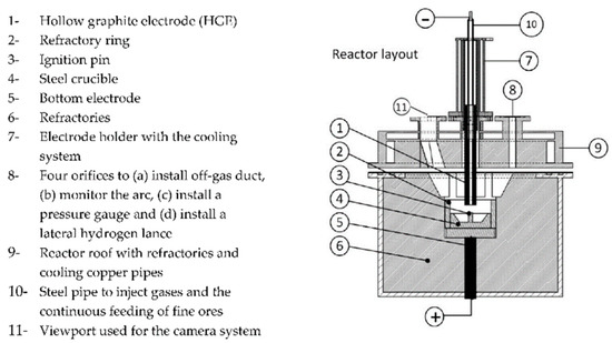
Figure 1. Schematic HPSR furnace layout reproduced under terms of the CC-BY license. Copyright 2020, the authors, published by MDPI.
The samples were charged batchwise in a steel crucible whose exact dimensions are summarized by Ernst et al.; all experiments were performed with 2 NL/min nitrogen purging. Table 2 summarizes the performed tests. Test 0 acts as a method test and is not further evaluated. In Test 4, 14.0 g CaO and 3.1 g MgO were continuously fed through a hollow electrode. Technically pure oxides with 95 and 99% purity from Carl Roth GmbH + Co. KG, Karlsruhe, Germany were used. Initially, the transformer current was set to 100 A. During the test, it was decreased stepwise, depending on the transformer temperature and voltage. For that, a silicon-controlled rectifier (SCR) was applied. In the final approx. 2.5 min of Test 4, the power input was maximized to intensify the slag–metal stirring.
Table 2. List of tests.
| Test | Gas | t/min | Sample | Mass/g | Comment |
| 0 | 2 NL/min N2 | 15 | 1 | 49.7 | Pretest |
| 1 | 15 | 1 | 101.6 | 0%C DR-grade-DRI | |
| 2 | 15 | 2 | 101.7 | 2.1%C DR-grade-DRI | |
| 3 | 15 | 3 | 100.4 | 0%C Fine-DRI | |
| 4 | 23 | 4 | 100.1 | 0%C BF-grade-DRI + Continuous feed of slag-forming oxides |
The experiments were evaluated in multiple ways. The HPSR reactor had an AXIS-Q1775 camera system (Axis Communications AB, Lund, Sweden) and a GAM 200 mass spectrometer (Pfeiffer Vacuum Technologies AG, Aßlar, Germany), which provide the possibility to monitor the electric arc as well as the off-gas. Further, voltage and current values were recorded and documented.
The crucibles were visually checked using a Sony Alpha 6000 DSLM camera (Sony Group Corporation, Tokyo, Japan) equipped with a Sigma Contemporary 30 mm lens (Sigma Corporation, Kawasaki, Japan). Afterward, the crucibles were embedded, cut, and the cross-sections were metallographically prepared. Figure 2 details the cutting scheme. Etching was performed using a 1% nital solution to highlight the transition between the crucible and the sample. We adjusted the time iteratively between 6 and 10 s.
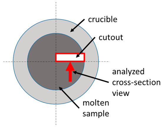
Figure 2. Location of metallographic sample.
The microsections were investigated using a Keyence VHX 7000 digital microscope (Keyence Corporation, Osaka, Japan). The chemical analysis of the gangue layer was performed via SEM-EDX Fei Quanta 200Mk2 (FEI Company, Hillsboro, OR, USA). Small samples were taken from two crucibles, Test 2 with carbonaceous DRI and Test 3 with DRI fines, to analyze carbon content using LECO. Test 3 can be considered representative for the carbon-free DRI tests.